Search This Blog

Friday, March 30, 2012

Initial Baffle Fitting


Here are some pictures of the initial fitting of the Baffles..  The more I learn about these the more nervous I get.  I spent a couple hours on the scotchbrite wheel fine tuning these to get them to fit around the cylinders.  My understanding from here is that you trim and fit the cowling, then trim some more and fit the cowling and trim some more, until you get the nice fit you are looking for.  Also, I have the horizontal aspirated engine which looks good from the outside, but requires that I fit the air intake (AKA Snorkel)) into the front ramp of the baffles.  The front ramp fitting is supposed to be the most difficult..   So we’ll see how this goes.


Thursday, March 29, 2012

Oil Door Latches


This piece of work took WAY longer than I had expected.   And it didn’t turn out quite as nice as I would have liked either.  But I don’t think you can get it any better, it is just the latches and fiberglass oil door don’t work super well together.  Plus the sanding involved getting these latches to fit was messy and time consuming.

But the latches fit quite flush and do look pretty good overall.  We’ll see if I can get them to look any nicer with some additional work.  You need two latches on the oil door because of the pressure inside the cowling.  It will pop open other less significant latches as the door flexes..   Plus I will put a layer or two of fiberglass on the inside of the door to help stiffen it up.  


Wednesday, March 28, 2012

Baffles


Over the next few months, things are going to be getting  a bit random with the build.  For example, I will be going back and forth between the Baffles and the Cowling for quite some time, then mixing it up with electrical and panel etc.  So with some initial work done on the cowling, for tonight it was time to start working with the baffles..

Baffles are used to force pressurized air over all parts of the engine ensuring that effective cooling takes place.  These are built in sections, then mounted around the engine completely encapsulating it so that all air coming in through the front of the cowl is strategically forced through the cooling fins of the engine.   You build them in 6 different sections and then start fitting them to the engine.   Here you can see all the sections starting to come together after a couple hours of de-burring and initial stiffener riveting.  It’s a bit confusing at first since there are so many parts, but close look at the plans and it all makes sense.


Monday, March 26, 2012

Continued with Cowling and started Oil Door

Some ups and downs in my recent work on the airplane.   I am excited about how the oil door has come together, but also made a mistake (recoverable) on the cowling..  So we’ll talk about the oil door first.  I got a “hidden” hinge on a previous order and was excited to finally be able to use it.   First I gut the square hole in the cowling just over ½ inch inside the edges of the indent for the oil door.  I rounded the edges and it looks pretty good.  Then I started drilling the two pieces of the hidden hinge.  I put a piece of .040 under the piece of hinge that attaches to the cowling to help offset the door so that it was flush when closed.  Also, the way I placed the hinge, it heat the upper section of my cowl cut out when I first functioned it.  Took off about 1/16 inch additional and am really happy how it finally turned out.   I have some “Hartwell” trigger lock flush latches on order that will be installed this week, to finish the door, apart from the riveting.   Also, I would not be nervous about making the door smaller than the “frame” on the cowling.  I have a good 1/8 inch outside of the door to the frame, which is good as it ensures a flush fit.  The additional space will be filled in later as I finish the cowling, to frame the door in nice and tight.

Onto the cowling.   I am happy the way it turned out, but after the fact realized I used the wrong hinges to secure the upper and lower cowl.   I used the hinge that was intended for the gear leg fairings.  It’s a very slightly smaller hinge and I assumed it looked good for the job.  Also, the hinge I was supposed to use I had previously used somewhere along the line,  probably for the seat backs, so I will need to order more.   The fix will be easy, just bummed due to the time involved.   But that said, the cowling now completely supports itself and I am really happy with the tightness and flush-ness of the install.   Hopefully when I replace the forward hinges I will be able to keep it the same.

Also, this weekend we had good weather for the first time since I could remember, so I pulled the plane out and let her see the sun for a while..


Monday, March 19, 2012

The Pepto Pink Cowl !

This weekend I started in earnest on the pink cowl.  First on the list is to start drilling the hinges to the forward top skin.  I used cleco clamps here and was able to get them drilled with the appropriate shims in place.  Then I added the other hinge (cowl side) using the full size aluminum hinge pin just to make sure I could get the pin through the hinge.  This will help make sure the hinges are inline, then when the plane is in finished I will replace this aluminum pin with a smaller (stronger) stainless steel pin.


After drilling the hinges, I pulled them off to start initial fitting of the pink cowl.   My initial take is that the cowl is going to be quite a challenge.  Lots of fitting and removing, and sanding, fitting removing and standing etc..   I trimmed the forward center flanges so that the spinner circle on the cowl was flush and as circular as possible.


Then before drilling anything the top half of the cowl, I test fit the bottom.  I trimmed the landing gear egress through the cowl, which took many more iterations that I had hoped.   I taped up the landing gear pretty good to protect from the abrasive cowl.  Getting it all together and roughly fit I am able to start seeing how this will go together.   The edges didn't overlap much if any at all.  I was worried a bit because some builders have had trouble with the cowl edges not being long enough.   By letting the cowl fall where it wanted and using some duck tape to pull up the edges, they eventually fit quite well.

After Fitting and sanding and fitting and sanding, I drew up the rivet lines on the top cowl at 1 inch apart and drilled the cowl to the hinge.  The cowl kind of has a mind of its own and wants to lie where it lies.   I had the bottom cowl taped up when I drilled the holes so that hopefully it was as square as possible. Seems to have turned out well so far.  The prop spinner is about exactly 1/4 from the cowl as indicated in the plans.


Saturday, March 17, 2012

Continued Engine Control work, Fuel Pump overflow and Pink Cowling?

I drilled a second hole in the mixture control arm which seems to be at the right distance from center to avoid interference with the starter and as well give enough throw in the mixture control.   All in all I think this will work out great.  I also used Permatex #2 and reinserted the ground down plug in the engine behind the mixture mechanism, as seen in the second photo.  Then I painted the plug using the touch up paint from Aerosport almost making the plug dissapear as seen behind the mechanism in the first photo.  ( I know very confusing) 


After that I started working with Fuel lines and the Fuel Pump overflow.  The fuel lines came with the firewall forward kit and I will be able to use most of them.  I will have to replace some though due to custom items I will be installing, like a fuel flow meter (red cube) etc..  

The Fuel Pump overflow is simply a tube from the fuel pump, that gets routed out away from the exhaust and through the bottom fuselage skin just aft of the cowling.  Turned out pretty good with some “rescue” tape under the high temp zip tie to protect the engine mount.

After that I decided to get a sneak peak at the top cowl.  Bekah grabbed a couple shots.

Sunday, March 11, 2012

Propeller, Exhaust, and engine control work

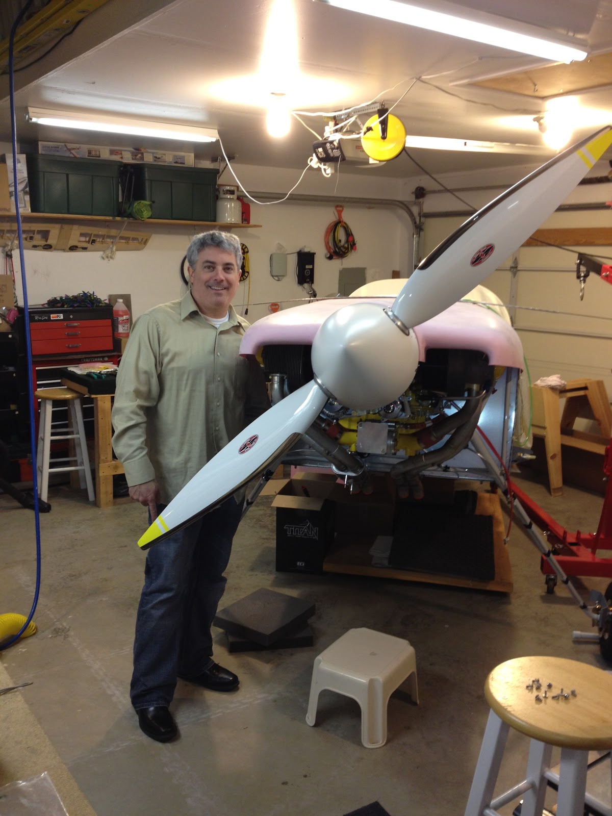
This weekend was jammed full of Airplane work.   I mounted the propeller on Friday, just to see how to do it and sure enough once you start you can't finish.  It took about 2 hours to screw the thing on because the bolts bind on each other if you turn any single one more than about 3/4 turn without catching the others up to it.  So basically each bolt you turn slightly, then turn all the others slowly and evenly pulling the prop to the flywheel case.   Getting the rear of the spinner on behind the prop is a different story, but I got her done.   I didn't torque the prop or safety tie it, but it seems to be on for good now.  It may need to come off, but hopefully not.

Then I started working on the Exhaust, which went on straight forward for the most part.  I had some troubles with the support tubes that slip inside the rubber sleeve and "hang" the exhaust from the engine mount.   These are shipped pretty long and need to be trimmed, but I was only able to figure that out after they were mounted..  I also temporarily fit the heater box which in an airplane is simply a box that feeds air over the exhaust to get it hot, then through the orange tube you see there goes into the cabin through the heat selector.

I also worked on both the Mixture control and Throttle control.  The throttle control although more work was straight forward and I am really happy with out it turned out.   You can see I had to fabricate a completely different mount than what came with the firewall forward kit.  The Cold Air Sump I have is quite different than the one vans expects to have on the IO-360..   You can see the one I made is similar, but complete different dimensions than the one supplied by Vans.   Primed, painted and installed.  The throttle functions quite smoothly.


The Mixture control, I was able to use Vans Mechanism for the most part.  There is a bit of a difference due to the cold air sump on this one too, and in fact I need to grind down an engine plug and fill the hole behind the mixture bracket "flush", but grinding the plug is taking longer than I thought, so I will get a picture of it once complete.  The challenge with the mixture is that the linkages seem to be just a bit long in all cases.   I pulled everything in as tight as I could, and actually drilled a closer in hole in the mixture arm.  Some builders buy a new arm that has a smaller radius, I am hoping I can get away with modifying the arm like I did.  In the end I might buy a new arm just the same, but this one seems to be working good.  There is not much throw now and I go from Full rich to Cut off in about 1.75 inches of the cable pull.   Will need to see if that is acceptable.   Other than the couple concerns, the mixture is coming along nicely.


Wednesday, March 7, 2012

Hung the Engine !


Big milestone reached today, but at this point big milestones are still just steps in the process.  As I look forward, there is still so much left to do.  Good thing I like building airplanes or else I would be in real trouble right now…   But yes, I was super excited to get the engine up on the plane.  I  think a key part of this task was the fact that I had a great hoist.  It allowed for very sensitive movements of the engine, which was way more critical than I thought.   As you raise it and move it back into place you really have to move it around to get it to fit back into the mount.  Also, as the $$$ engine is hanging by the hoist, it is a little nerve racking.  Here are a few pics of the set up.  I had the rear of the plane up on a saw horse and the hoist raised it right up to the mount.


I started by following the Vans instructions of inserting the lower bolts first.  I would recommend not to do this, after I had two in and couldn’t get the third I pulled them and started at the top.  The reason these bolts are hard to insert is because the rubber mounts only fit perfectly when compressed.  They are all off until you suck the engine back into the mount but you can’t suck it back until the bolt is in place.  So you go one at a time and through tightening and loosening you can eventually get them all in.  Starting from the top, you can then use the weight of the engine to compress the lower mounts and get someone better fit.  Anyway, the 4th bolt was a pain, but it went in with a little finesse..  Below on the right is the last bolt slipping in..  Notice the upper and lower rubber mounts are reversed to account for the different forces that the engines weight puts on the mount..   (pull on top, push on bottom)


Now she is hung and I still have to torque and install cotter pins, but all in all I am ready to really dig into the firewall forward stuff now.


Monday, March 5, 2012

Prop and Governor

This weekend I went over to Eastern Washington to pick up my Propeller..  I won't go into details why I had it shipped into an Idaho location then picked up by my friend, but the point is I have m prop now.   Its a WW 200RV constant speed prop.  Carbon fiber blades with a nickel metal leading edge.  Its about 18 pounds lighter than the equivalent aluminum prop.  I am super excited to have this in my hands now..  I went with yellow tips, but they came out a bit lighter than I would have liked, but no looking back now so I will love them and move on.  Here are some pics from the I-phone:


I also picked up the PCU-5000X governor which basically allows me to adjust the RPM to a "constant speed".  This ties into the backside of the engine and powers to pitch of the prop via oil pressure.   I used the standard Van's Mount for the cable, but had to modify the holes a bit and deepen up the curve that fit on the governor..  Not to much work and it fits great.   I was confused a bit on the gaskets since it looks like there is an extra hole in the gasket that is not in the governor mount.  Maybe it is so you can reverse the gasket?  But the screen is bowed out, so no way to reverse the gasket..  I need to verify the way I mounted this and determine the final torque values for the governor bolts, then I will be wrapped up and ready to hang the engine.  I had some extra time so I test fit the cable, works great.  After these photos I re-installed the safety wire that had to be removed to fit the cable bracket.  I learned that Safety tying wire is an art, and after a few attempts I got all the screws to the point where I was comfortable.


Places we have been in our RV-7 ! (Blue 2013, Yellow 2014, Green 2015, Purple 2016, Red 2017)